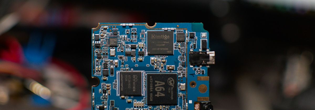
Doubling the PinePhone storage perf with a soldering iron and a steady hand
There have been some recent waves in the Pine64 community thanks to a new mod which can drastically improve eMMC speed!

There have been some recent waves in the Pine64 community, as user Federico Izzo (@_symmetrist_) found a PinePhone mod which can roughly double the eMMC speed simply by moving a single resistor. But, anyone can write a flashy headline, how the heck does this actually work?
Federico did a write-up on their blog which explains where they got the idea from and how to perform the mod for yourself, as well as how distros can support the mod. Thanks to this it is now already supported in postmarketOS!
To summarise, the PinePhone eMMC ships in the "DDR52" timing mode by default, which modes are allowed depends on the eMMC controller voltage (this voltage is supplied by the VCC-PC power rail and provides power to the eMMC controller). DDR52 is the highest timing mode supported at 3.3v, which is what the PinePhone uses. To run this any higher, the supply must be at 1.8v or 1.2v.
The electronics-minded among you may have a few ideas on how you could go about this, if you already know how it's done, suspend your disbelief for a short moment.
One potential solution would be to use an LDO (Low-Dropout) voltage regulator, these take some higher input voltage and convert it to a lower output voltage, but that would get pretty fiddly. If you're familiar with embedded platforms you might know that a lot of power management chips actually have configurable regulators, where the voltage can simply be adjusted at will. Unfortunately, the eMMC controller isn't provided by a supply with that capability. Perhaps there's another 1.8v regulator that could be used via a jumper, this is a good bet and I'm sure there would be a way to make that work. But luckily for us it's even easier!

When designing embedded platforms, there is often a need to denote many different power rails, this can help with managing current limits (to avoid burning up the circuit board traces), to easily differentiate rails that can be turned on/off to save power - Even if they're running at the same voltage - or for a myriad of other reasons I won't go into here. In this case, the VCC-PC power rail is "derived from" the DCDC1 rail. DCDC1 is a fixed 3.3v regulator, provided by the power management IC on the PinePhone, it passes through a 0Ω (that is, zero ohm) resistor and the output is called VCC-PC.
Phew, hope I didn't lose you there, we're almost done.
You might be wondering what the purpose of a 0Ω resistor is, they're actually surprisingly common, usually to allow for multiple configurations which can be selected when the device is being put together at the factory, to handle different add-ons or features by either populating the resistor, or leaving it unpopulated. R615 in the above screenshot is an example of that.

That is also the case for resistor R614 shown in this screenshot, it shows that VCC-PC can be derived from CPVDD, but the default configuration is that it is left disconnected.
And, the magic moment, CPVDD is a 1.8v regulator! So, it's as simple as desoldering R615 and placing it on R614 (or even just making a big blob of solder on R614).
The end result is as a relatively straightforward mod for anyone with some soldering experience, it should also be relatively safe as it's clear that the schematics and board design account for this capability.
It is surprisingly common for manufacturers to leave in alternative hardware configurations, simply deriving multiple products from the same design. This has lead to all sorts of fun hardware mods over the years, and hopefully many more to come!


Comments ()